
FDB20_0001
High pressure directional valves VD
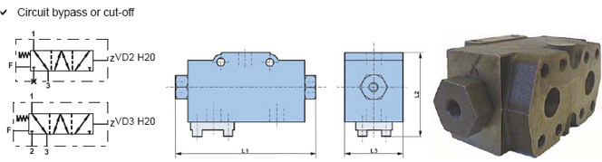
| Directional valves | VD2 H20 | VD2 H25 | VD3 H20 | VD3 H25 | |
|---|---|---|---|---|---|
| Function | Locking | Locking | Electrical / Mechanical | Metric - Gas - UNF | |
| Nominal flow | L/min [GPM] | 130 [34.3] | 260 [68.7] | Electrical | Metric - Gas - UNF |
| Max. pressure | bar [PSI] | 450 [6 526] | |||
| L1 max. | mm [in] | 188 [7.40] | |||
| L2 | mm [in] | 130 [5.12] | 130 [5.12] | 100 [3.94] | 100 [3.94] |
| L3 max. | mm [in] | 84 [3.31] | 84 [3.31] | 84 [3.31] | 84 [3.31] |
| Weight | kg [lb] | 8 [17.5] | 8 [17.5] | 8 [17.5] | 8 [17.5] |
Flow Divider FDB 20
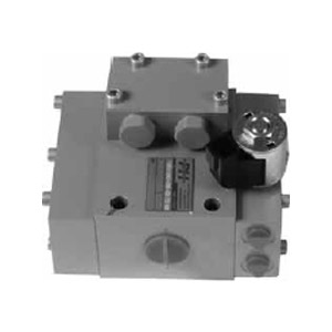
Features
- Up to 450 bar (6 527 PSI)
- Up to 150 L/min (39.6 GPM)
- Direct in-line mounting.
- Threaded connections to ISO 1179 (BSPP/Gas), ISO 11926 (UNF).
Operation
The bidirectionnal flow divider controls the speed between wheels of the same axle or between different axles by dividing or combining the flow.
The flow divider is equipped with an electric or hydraulic controlled by-pass and can be used in open or closed loop circuits.

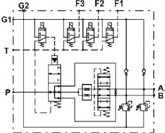
Hydraulic symbol
HP valve, 3 solenoid valves and electric by-pass
HP valve and hydraulic by-pass
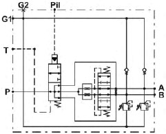
P: High pressure
A and B: Outlet
T: Drain
G1: Preferential charge pressure
G2: Plugged charge pressure
Pil: Hydraulic control
F1, F2 and F3: Solenoid valves
Features
| Max. pressure | bar(PSI) | 450 [6 527] | |
|---|---|---|---|
| By-pass mini. piloting pressure | bar(PSI) | 8 [116] | |
| Max. flow in by-pass mode | L/min[GPM] | Ratio50/50 Ratio60/40 Ratio70/30 Ratio75/25 Ratio80/20 | 150 [39.62] 125 [33.02] 110 [29.05] 100 [26.41] 95 [25.09] |
| Mass | kg[lb] | without valves with HP valve with HP valve and 3 solenoid valves | 8.50 [18.74] 9.00 [19.84] 11.2 [24.70] |
| Surface treatment | Zinc Chromate |
| Pressure drop in by-pass mode |
|---|
| Test Conditions : HV 46 hydraulics fluid at 40°C [104°F] |
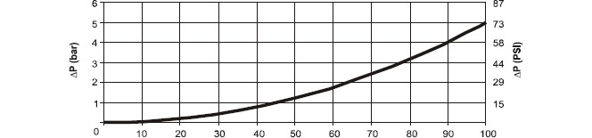 |
| % of input flow (Qp,c) |
| Pressure drop in divider mode |
|---|
| Test Conditions : HV 46 hydraulics fluid at 40°C [104°F] |
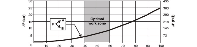 |
| % of controlled flow on input P (Qp,c) |
| Division Accuracy | |
|---|---|
| Test Conditions : P of 150 bar [2 175 PSI] between otlets. No transfer restrictor HV 46 hydraulic fluid at 40°C [104°F] | 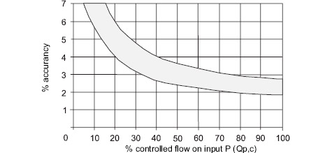 |
| Max. pressure | ||
|---|---|---|
| Transfer restrictor is located between the outlets A and B. |  | * Standard values ** On request, after validation of your application |
| Pressure drop in charge check valve |
|---|
| P=5 bar [72.52 PSI] for a flow of 20 L/min (between A or B and G1) P=up to 30 bar [435 PSI] for a flow of 20 L/min (between A or B and G2) |
